Reading Material
Introduction Lesson 1 of 24
In Progress

Data vs Information

The terms "data" and "information" are often used interchangeably, but there is a subtle distinction between the two. In essence, data can be any number, symbol, character, word, code, graph, or other representation. Information, on the other hand, is data placed into context and utilized by humans in significant ways, such as decision-making and forecasting.

Data refers to raw facts and figures that can be stored and transmitted, becoming information after processing. Information enables decision-making, particularly in the context of data communication, where information is transmitted in the form of messages, including text, images, audio, video, and other media, encoded into electromagnetic signals for transmission over a physical medium.

A basic example of information is a computer, which uses programming scripts, formulas, or software applications to transform data into information. The difference between data and information can be summarized in the following table:

Difference between Data and Information:

Data

Information

Data is unorganized and unrefined.

The information comprises processed, organized data presented in a meaningful context.

Data is an individual unit with raw materials lacking specific meaning.

Information is a group of data collectively carrying a logical meaning.

Data doesn't depend on information.

Information depends on data.

Raw data alone is insufficient for decision-making.

Information is sufficient for decision-making.

Example: A student's test score.

Example: The average score of a class derived from the given data.

Data Representation

Let's talk about how we show data. Remember, data is like the building blocks that we turn into useful information. Now, data can be shown in different ways.

Types of Data

  • Text: It's like the words you're reading now, with both small and big letters. Computers store text as a pattern of bits. They use codes like ASCII and Unicode to do this.
  • Numbers: Numbers are combinations of digits from 0 to 9. Computers store them as patterns of bits, too, using codes like ASCII and Unicode.
  • Images: Pictures are stored digitally in computers. Imagine a picture made up of tiny dots called pixels. So, a picture is basically a grid of these pixel dots.
  • Audio: Sound can also be data! Think of what you hear on the radio. Audio data is continuous, like a flowing stream of sound.
  • Video: Videos are like moving pictures with added sound.

Analog and Digital Data

When we want to send data, we turn it into electromagnetic signals. These signals can be either analog or digital.

  1. Analog Data: It's like smooth waves that represent information continuously. For example, when someone sings, the sound waves are analog. We can capture them with a microphone and turn them into signals for transmission.
  2. Digital Data: This is more like building with blocks. Computers store data as 0s and 1s, and we can convert these into digital signals or even into analog signals for transmission through a medium.

So, in simple terms, data can be text, numbers, images, audio, or video. And when we send it, it can be in the form of smooth waves (analog) or building blocks (digital).

Summary:

In this article, we found out what Data is and what Information means. Simply put, data is like a messy collection of raw facts, and from this, we can get organized and useful information.

Reading Material
Introduction Lesson 2 of 24
In Progress

Data Communication

Data communication is like a conversation between devices, such as computers, phones, and laptops. They share different types of information like text, images, audio, and video. Think of it as a network of connected devices, like in the Figure below, where computers, printers, servers, and switches are linked.

Data Communication between the LAN

In simple terms, data communication is about passing information from one place to another. It happens between two devices using a pathway called a transmission medium. This system involves hardware (like sender and receiver devices) and software (protocols that guide the communication). It's like a well-coordinated dance between devices, making sure the information gets where it needs to go.

Key Aspects of Data Communication

For a data communications system to work well, it needs to have these four important features:

  1. Delivery: Make sure the data reaches the right place and the correct person. It's like making sure your message gets to the right friend without any mix-ups.
  2. Accuracy: The communication system must send the data without making mistakes. Sometimes, during the journey, the data can get mixed up or changed. We want to prevent that to make sure the information is correct when it reaches its destination.
  3. Timeliness: When we're dealing with audio or video data, it must reach its destination quickly and without delays. Imagine having a phone call or watching a video in real-time; that's what we call real-time transmission of data.
  4. Jitter: Jitter is like the ups and downs in the arrival time of data. We want to avoid uneven jitter because it can mess up the timing of the data being sent. Think of it like trying to play music smoothly without any interruptions.

Components of the Data Communication System

When we talk about devices communicating through a network, we think about five important parts.

These are the sender (a device that sends data), receiver (a device that receives data), communication medium (the path for data to travel), message (the information being sent), and protocols (rules for communication). The communication medium is also known as transmission media.

  • Sender: This is a device like a computer, phone, watch, or any other gadget that can send data over a network.
  • Receiver: This is a device, like a computer, printer, phone, or TV, that can receive data from the network. In computer talk, we call the sender and receiver "nodes" in a network.
  • Message: This is the information or data that needs to go from the sender to the receiver. Messages can be text, numbers, images, audio, videos, or other types of data.
  • Communication Media: It's the path the message takes from the sender to the receiver. This can be wired (like cables) or wireless (like satellite links or microwaves). For example, TV cables, telephone cables, Ethernet cables, and satellite links are types of communication media.
  • Protocols: These are rules that everyone has to follow to make sure communication works well. You might have heard of protocols like Ethernet and HTTP. They help in making data communication successful and reliable.
     

Measuring Communication Media Capacity

In data communication, the path where information travels is called a channel. The channel's capacity is like its traffic limit—how much data it can handle. We measure this capacity using two things: bandwidth and data transfer rate.

1. Bandwidth:

  • Bandwidth is like the road width for data. The wider the road, the more cars (or data) can pass through.
  • It's measured in Hertz (Hz), which tells us how much data the channel can handle at once.
  • Example: If the bandwidth is 1000 Hz, the channel can handle 1000 pieces of data in one go.

2. Data Transfer Rate:

  • Think of the data transfer rate as how fast the data travels on the road.
  • It's measured in bits per second (bps), showing how many bits move from one place to another in one second.
  • Example: If the data transfer rate is 1 Kbps, it means 1000 bits of data move in one second.
  • Units for Data Transfer Rate:
    •    - 1 Kbps = 210 bps = 1024 bps
    •    - 1 Mbps = 220 bps = 1024 Kbps
    •    - 1 Gbps = 230 bps = 1024 Mbps
    •    - 1 Tbps = 240 bps = 1024 Gbps

In simple terms, bandwidth is like the road's width, and the data transfer rate is how fast the data travels on that road. The bigger the bandwidth and data transfer rate, the more and faster data can be sent through the channel.

Reading Material
Introduction Lesson 3 of 24
In Progress

Data Transmission Modes

Data communication involves the exchange of signals between computing devices or nodes. Data transfer occurs through either a point-to-point or multipoint communication channel. There are three main types of data communication modes:

1. Simplex Communication:

Simplex communication is a one-way or unidirectional interaction between two devices, where one device serves as the sender, and the other as the receiver. In this mode, the entire link capacity is utilized for transmitting data. It resembles a one-way street, allowing communication only in a single direction. Examples include data input from a keyboard or audio output to a speaker. An illustration of simplex communication is controlling home appliances through IoT, such as managing fans, lights, and other devices remotely.

Simplex One Direction

2. Half-duplex Communication:

Half-duplex communication enables bidirectional data exchange between two devices. Both devices can send and receive data or control signals, but not simultaneously. It operates like sharing a one-way narrow bridge, allowing traffic in both directions but not simultaneously. An example is a walkie-talkie, where pressing the push-to-talk button enables transmission while disabling reception, allowing others only to listen. The direction of transmission can be switched in this type of communication.

Half-duplex Communication

3. Full-duplex Communication:

Full-duplex communication allows bidirectional data exchange between devices simultaneously. It resembles a two-way road where vehicles can travel in both directions simultaneously. This communication mode is commonly employed in mobile phones and landline telephones. The transmission link's capacity is shared between signals moving in both directions. This can be achieved using two physically separate simplex lines—one for sending and another for receiving—or by sharing the capacity of a single channel between signals in different directions.

Full-duplex Communication
Reading Material
Introduction Lesson 4 of 24
In Progress

Basics of Computer Network

A computer network is like a team of connected computers and devices that talk to each other using a common language. They share stuff, like sending and getting data, over a network, which is like a virtual highway for information.


When computers or devices can talk and exchange info, we say they are " interconnected ." Each computer or device is called a "node," and anything that can send or receive data can be a node too. They talk through " communication links ," which are like the roads connecting them.

The main reason for having a computer network is to share things. Nowadays, most networks share a link to the internet, but they can also share things like printers or file servers.

Need for Computer Networks

The important motivations for a computer network include the following.

  • Sharing of resources such as printers and expensive software and databases.
  • Serves as communication media for long-distance communication
  • Provides high reliability and availability of data and information among the users of the network.
  • Provides economy of data storage and communication
  • Scalable to accommodate an increasing number of users
  • Offers centralized administration
  • Connects people, buildings, and organizations

Components of a network

 Following are some of the major components of a computer network.

  1. Computers or workstations
  2. Servers such as File Servers, Print Servers, Database Servers etc.
  3. Printers, Faxes
  4. Interconnecting devices such as switches, hubs, routers, bridges, gateways, etc.
  5. Connectors, cables(coaxial, twisted pair or fiber optic)
  6. A Network Interface Card (NIC) in each computer
  7. Network Operating Systems

Advantages of Computer Networks

Following are some of the advantages of a computer network

  1. Increased Speed: The network provides the fastest medium of data communication
  2. Reduced Cost: It reduces the storage maintenance and data transfer cost per unit.
  3. Improved Security: It is now possible to protect the programs and files from illegal access.
  4. Centralized Administration: A centralized server can store important software and provide controlled access to many users.
  5. Flexible Access: The authorized user can access their files from any computer connected to the network.

Disadvantages of Computer Networks

The major disadvantages of a computer network are as follows:

  1. High cost of installation: The initial cost of installation of a computer network is high.
  2. Maintenance cost: It requires proper and careful administration and maintenance by a specialized technical person.
  3. Failure of Server: If the file server goes down then the entire network comes to stand standstill.
  4. Cable fault: The computers in the network are connected with the help of cables. If the backbone cable fails it causes the entire network failure.
     

Network Criteria

The most important criteria for a network to be efficient are performance reliability and security.

Performance

  • The performance of a network can be measured in many ways including transit time and response time.
  • Transit time is the amount of time required to transmit a message from one device to the other.
  • Response time is the time elapsed between a request and a response.
  • The performance of a network can be ensured by achieving higher throughput and smaller delay times.
  • The performance of a network also depends on other factors including the following.
    1. Number of users
    2. Type of transmission medium
    3. Network hardware and software.

Reliability

The reliability of a network depends on accuracy, frequency of failure, the time it takes to recover from failure, and robustness in a catastrophe. A computer network is said to be reliable if it provides a higher level of accuracy, less frequency of failure, less recovery time, and robust to catastrophic failure.

Security

Network Security issues include protecting data from unauthorized access, viruses, and different types of attacks to access network resources.

The network protocols provide security mechanisms to ensure the protection of data from unauthorized access. A good network is protected from viruses by specifically designed hardware and software.

Reading Material
Networking Essential Lesson 5 of 24
In Progress

Network Topology

In computing, the organization of network devices is crucial for visualizing, monitoring, and diagnosing network issues. The term "Network Topology" defines how nodes interact to manage data flow, with "Topology" originating from Greek words meaning the study of the geographical arrangement. Topology encompasses the logical or physical connection and arrangement of nodes for information sharing.

Upon completing this article, you'll be equipped to define network topology, differentiate between various network topologies, categorize them, and elucidate the characteristics of the following topologies: Bus, Ring, Star, and Mesh.

Understanding Network Topology

Network topology refers to how computers or nodes are connected in a network. It is a visual representation of the arrangement of nodes and connecting lines in a network. Each topology serves specific purposes and comes with its pros and cons. The choice of topology depends on factors like the type and number of devices, data transfer speed, planned applications, response time, and cost.

There are two fundamental types of network topology:

  • Physical Topology
  • Logical Topology

Physical topology illustrates the placement of devices and cables in the network, while logical topology focuses on the flow of information (data) in the network, independent of physical design. While the distances between nodes, physical connections, transmission rates, and signal types may differ, two networks can have the same topology.

For communication to occur, devices must be connected to the same link simultaneously. There are two possible types of connections:

  1. Point-to-point connection
  2. Multipoint Connection

i. Point-to-Point Connection:

Point-to-point networks involve precisely two hosts, such as computers, switches, routers, or servers, connected directly using a single cable. Typically, one host's receiving end is connected to the sending end of the other, and vice versa. In a point-to-point network, if composed of multiple connections, data packets must traverse various intermediate devices. The links between these devices may have different lengths, emphasizing the importance of minimizing the distance to reach the receiver.

Point-to-point Connection

ii. Multipoint Connection:

In a multipoint connection, more than two devices share a single link. In this setup, the channel's capacity is shared either spatially or temporally. Each device in a multipoint connection must have a means of identifying itself and the intended recipient, accomplished through addressing. In a broadcast network, where multiple devices share a link, each device processes the transmitted packet. The receiver, identified by the packet's address field, determines whether to keep or discard the packet based on whether it belongs to that specific device.

Multipoint Connection


Key Differences between Point-to-Point and Multipoint Connection:

Key Differences

Point-to-Point Connections

Multipoint Connections

1. Link Configuration

Involves a dedicated link between two devices.

Shares a single link among more than two devices.

2. Channel Capacity

Reserves the entire channel capacity for the two devices involved.

Shares channel capacity provisionally among connected devices.

3. Transmitter and Receiver

Has a single transmitter and a single receiver.

Has a single transmitter and multiple potential receivers.

4. Simplicity

Generally simpler to set up and manage due to the direct connection.

Complexity may increase as the number of devices sharing the link grows.

5. Resource Utilization

Efficient utilization of channel capacity for the dedicated link.

Channel capacity may experience contention and less efficient utilization.

6. Scalability

It may be less scalable for a large number of devices due to individual links.

More scalable as additional devices can share the existing link.

7. Network Performance

Often provides better performance for point-to-point communication.

Performance may be impacted when multiple devices contend for the shared link.

8. Cost

Potentially lower cost for a simple, direct connection.

Costs may increase with the need for more sophisticated multipoint configurations.

It's worth noting that in a network, both logical and physical topologies can be either identical or different. The four fundamental topologies are Bus, Star, Ring, and Mesh.

Types of Network Topology

Network topology, a geometric representation of a network, defines how devices (nodes) are interconnected. The common network topologies include:

1. Bus Topology:

In a bus network, all workstations connect to a single cable (Linear Bus) terminated at each end. Nodes, including file servers and peripherals, connect to the main cable through drop lines and taps. Signals are broadcast to all stations, but each station acts only on frames addressed to it.

Bus Topology


   Advantages of Bus Topology:

  • Easy initial set-up of a linear bus.
  • Simple connection of computers or peripheral devices.
  • Hardware reliability is higher.
  • Scalable; easy to extend as the network grows.
  • The coverage area can be increased using repeaters.

   Disadvantages of Bus Topology:

  • Cable break affects the entire LAN.
  • Fault diagnosis is challenging, requiring detection from multiple points.
  • Nodes need to be intelligent for protocol operation.
  • Terminators are required at both ends of the backbone cable.

2. Star Topology

In a star network, each workstation connects to a central controller, known as the hub, switch, or concentrator, via a dedicated cable. Data within the star network flows through the central controller before reaching its destination, with the controller managing all network functions and serving as a repeater for data transmission.

Star Topology

Advantages:

  • Easy installation and maintenance.
  • Requires fewer cables compared to mesh networks.
  • Localizes link failures, preventing impact on the entire network.
  • Nodes can be added or removed without disrupting the network.
  • Fault detection and component removal are straightforward.

Disadvantages:

  • Requires more cable than bus topology.
  • Network failure occurs if the central controller fails.
  • Limited scalability for the number of nodes in the network.
  • Higher cost compared to linear bus topologies due to hub or concentrator expenses.

3. Ring Topology

In a ring network, a closed loop of cables is formed where each workstation connects to two adjacent workstations, creating a continuous ring. Data circulates around the ring in a unidirectional manner, passing through workstations until reaching its destination. Each workstation functions as a repeater, forwarding the message to the next workstation. The response time of a ring network is influenced by the number of workstations, with more workstations leading to slower LAN performance.

Ring Topology


Advantages:

  • Requires less cabling compared to other topologies.
  • Performs efficiently under heavy network loads, outperforming a star topology.

Disadvantages:

  • A cable break between devices impacts the entire LAN.
  • Higher implementation cost is associated with ring topology, primarily due to the increased cost of token ring network adapter cards compared to Ethernet cards.

4. Mesh Topology

In a mesh topology, each computer establishes dedicated point-to-point links with every other computer. A fully connected mesh network comprises n × (n-1) cable links for n devices, requiring each node or device to have (n-1) connection points.

Mesh Topology


Advantages:

  • Dedicated links eliminate traffic issues.
  • Fault detection and isolation are straightforward.
  • Robust, as the failure of one link does not impact others.
  • Provides enhanced security and privacy.

Disadvantages:

  • Redundant paths in the network make it more complex.
  • Installation costs are high due to extensive cabling.
  • The number of input/output ports is significant.

Comparison of Network Topologies: 

Topology

Use

Pros

Cons

Bus

Central logical topology for Ethernet

Ease of initial set-up, Low implementation costs

Cable breaks affect the entire network

Star

Central physical topology for various logical implementations

A cable break usually affects only one workstation. Easy addition of workstations

Excessive cable costs due to the distance factor

Ring

Central logical topology for Token Ring and FDDI

Uses less cabling

Cable breaks between devices or node failure affect the entire network and Higher implementation costs

Mesh

Point-to-Point topology

Robust

Uses more cabling

Top of Form

Reading Material
Networking Essential Lesson 6 of 24
In Progress

Types of Computer Network

Computer networks come in diverse forms, spanning from handheld devices such as mobile phones and tablets linked via Wi-Fi or Bluetooth within a confined space to expansive networks comprising millions of computers worldwide. Connectivity varies, with some networks utilizing wireless links and others relying on wired connections.

These networks are broadly categorized based on the geographical area covered and data transfer rate:

Local Area Network (LAN):

A Local Area Network (LAN) connects networking devices within a single office, building, or campus, tailored to the specific needs of organizations. Typically covering a few kilometers, a LAN is established to facilitate communication within a localized environment. In educational institutions, for example, interconnecting computers across classrooms or laboratories forms a LAN.

Local Area Network

The primary purpose of a LAN is resource sharing, encompassing both hardware and software. Shared hardware resources may include printers and scanners, while software resources comprise data, tools, and programs. Historically, LAN speeds ranged from 4 to 16 Mbps, but contemporary LANs can achieve speeds of 100 to 1000 Mbps.

Interconnection within a LAN is often facilitated by central devices such as switches or hubs. The prevalence of Wireless LANs (WLANs) is on the rise due to their cable-free or minimal cabling setup, providing increased flexibility. The diagram illustrates a typical Local Area Network configuration.

Wide Area Network (WAN):

Wide Area Network (WAN) is structured for the transmission of data over long distances. Its coverage extends to vast geographical areas, encompassing countries, continents, or even global connections. Notably, the entire worldwide internet infrastructure is a prime example of a WAN.

When the WAN of one country or continent interconnects with another, it forms a broader WAN. Consequently, the internet serves as the amalgamation of Wide Area Networks from all countries across the globe.

Wide Area Network (WAN)

WANs can be established through wired connections, wireless technologies, or a combination of both, providing flexibility in connectivity options.

Metropolitan Area Network (MAN):

A Metropolitan Area Network (MAN) falls in size between a Local Area Network (LAN) and a Wide Area Network (WAN). Typically, it extends within the boundaries of a city or town, serving as a network infrastructure for urban areas.

Metropolitan Area Network (MAN)

MANs offer high-speed connectivity to customers within a metropolitan region. This is exemplified by services such as high-speed internet from a TV cable operator or the deployment of DSL lines by a telephone company across a city.

Personal Area Network (PAN):

A Personal Area Network (PAN) is a compact network designed to link devices within an individual's personal space. An illustrative example is the connection established between a smartphone and a laptop using Bluetooth technology.

Personal Area Network (PAN)

Home Area Network (HAN):

A HAN is a network within a home that connects various digital devices. It allows devices like computers, smartphones, smart TVs, and appliances to communicate with each other.

Home Area Network (HAN)
   

Campus Area Network (CAN):

A CAN interconnects multiple LANs within a specific geographic area, such as a university campus. It provides high-bandwidth connections between different buildings or departments.

Campus Area Network(CAN)
   

Storage Area Network (SAN):

A SAN is a dedicated network that provides access to consolidated, block-level data storage. It allows multiple servers to access storage resources independently.

Wireless Local Area Network (WLAN):

A WLAN uses wireless communication protocols (like Wi-Fi) to connect devices within the coverage area. It's common in homes, offices, and public spaces.

Wireless Local Area Network (WLAN)
 

Virtual Private Network (VPN):

A VPN creates a secure, encrypted connection over the internet, allowing users to access a private network remotely. It is commonly used for secure remote access to corporate networks.

Virtual Private Network (VPN)

Intranet:

An intranet is a private network within an organization that uses internet protocols and technologies but is isolated from the global internet. It's used for internal communications, file sharing, and collaboration.


Reading Material
Network Reference Models: OSI & TCP/IP Lesson 7 of 24
In Progress

Introduction

In addition to protocols, it's crucial to understand the role of addressing in data communication. Addressing involves assigning unique identifiers to devices and systems within a network, facilitating accurate data transmission. Each device on a network has a distinct address that helps in routing information to the correct destination.


Furthermore, data communication often involves the concept of encapsulation, where data is wrapped in a specific format before transmission. This encapsulation process helps in organizing and structuring data, ensuring that it can be correctly interpreted by the receiving device.

Another important aspect is the distinction between analog and digital signals in data communication. Analog signals represent continuous waves, while digital signals are discrete and take on specific values. The conversion between these signal types is crucial in modern communication systems, as digital signals are more resilient to noise and distortion.

Security is a paramount concern in data communication. Encryption plays a pivotal role in safeguarding sensitive information during transmission. It involves encoding data in a way that only authorized parties can decipher, adding a layer of protection against unauthorized access or interception.

Additionally, Quality of Service (QoS) mechanisms are implemented to prioritize and manage the flow of data in a network. QoS ensures that critical applications receive sufficient bandwidth and resources, optimizing the overall performance of the communication system.

In the context of network models, it's worth noting that the OSI (Open Systems Interconnection) model consists of seven layers, each responsible for specific aspects of communication. These layers include the physical, data link, network, transport, session, presentation, and application layers. Similarly, the TCP/IP model, which is widely used in internet communication, comprises the link, internet, transport, and application layers.

Understanding these additional elements enhances the comprehension of data communication, providing a comprehensive view of the various factors at play in efficient and secure information exchange across networks.

This article will help you:

  • Grasp the importance of network reference models
  • Recognize the advantages of layered architecture in network models.
  • Enumerate the seven layers of the OSI reference model
  • Understand the operations of the OSI layers and the services they provide.
  • Compile a list of functions and responsibilities of each OSI model layer
  • Understand the operations of TCP/IP layers and their respective services.
  • Compile a list of functions and responsibilities of each TCP/IP model layer
  • Summarize the roles of OSI layers and compare them with the functions of TCP/IP layers.
// Add collapsible behavior const coll = document.getElementsByClassName("collapsible"); for (let i = 0; i < coll.length; i++) { coll[i].addEventListener("click", function () { this.classList.toggle("active"); const content = this.nextElementSibling; if (content.style.display === "block") { content.style.display = "none"; } else { content.style.display = "block"; } }); }
Reading Material
Network Reference Models: OSI & TCP/IP Lesson 8 of 24
In Progress

Network Models

A network model encompasses the design of a computer network, comprising hardware, software, access methods, and protocols. It serves as a conceptual framework for communication between computers and typically adopts a layered structure.

Layered Architecture of Network Models

Communication in a computer network involves a layered structure where corresponding layers perform similar functions for both senders and receivers. A shared language, known as a protocol, facilitates conversation. 

Benefits of Layered Architecture:

The layered architecture brings forth several advantages, including:

  • Easy Debugging: Simplifies the identification and resolution of issues in network applications.
  • Simplified Network Management: Structured architecture streamlines the management of network components and operations.
  • Adherence to Protocols: Network layers follow predefined rules, encapsulated in protocols, ensuring standardized communication.
  • Protocol-Defined Handshakes: Protocols dictate the data format, control, and timing for seamless interactions between layers.

Layered Task

The primary objective of a computer network is to transfer data from sender to receiver. This intricate task is deconstructed into well-defined subtasks, each with its distinct processes, inputs, and outputs, collectively referred to as layers. This layering approach, a fundamental principle, is universally applicable to various job domains.

Illustrating the Necessity of Layering:

To illustrate the necessity of layering and the use of common protocols for communication in network architecture, consider an analogy from daily life: two friends communicating through postal mail in a step-by-step manner. This scenario helps elucidate the importance of layering and protocol-defined communication in network architectures.

Example of Layered Task

Reading Material
Network Reference Models: OSI & TCP/IP Lesson 9 of 24
In Progress

OSI Reference Model

Before we delve into the ISO-OSI model, let's understand its significance and purpose.

  • The ISO-OSI model, developed by the International Organization for Standardization (ISO) in 1984, is the cornerstone architectural model for inter-computer communications.
  • Functioning as a descriptive network scheme, this model ensures enhanced compatibility and interoperability across diverse network technologies.
  • It serves as a guide, illustrating the journey of information or data as it traverses from one application program through a network medium to another application program on a different network.
  • The model intelligently breaks down the complex task of moving information between computers over a network medium into seven more manageable and modular problems.

By adopting the ISO-OSI model, we achieve a structured approach to understanding and resolving the intricacies of inter-computer communication within a network.

Seven Layers of the OSI Model

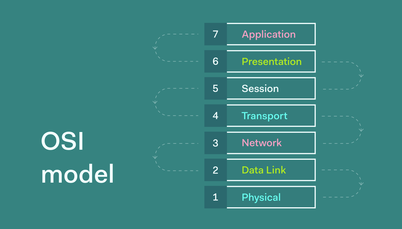
The OSI Model is like a seven-story building; each floor has its own job. Remember the order with phrases like "Please Do Not Take Seriously Peculiar Analogies" or "All People Seem to Need Data Processing."  

1. Layered Structure:

  • Think of the OSI Model as a building with seven floors. Each floor (layer) has a specific job in making networks work.
  • The bottom four floors (1-4) use both hardware and software and deal with how data moves. The top three floors (5-7) mainly use software and focus on helping applications.

2. Communication between Layers:

  • Imagine messages going down through the floors. Each floor adds something to the message.
  • When a device sends a message, it asks for help from the floor below. The receiving device takes away the added stuff from each floor.
  • Floors at the same level in different devices talk to each other, like neighbors. This is called peer-to-peer communication, helped by interfaces.

Peer-to-Peer Communication

Picture each floor talking to its buddy on the same level in another device, using specific rules (protocols). Interfaces are like a language that helps each floor know what services to provide, making sure they understand each other.


3. Encapsulation and Decapsulation:

  • Imagine adding a cover (header) before and after a message at the sender – that's encapsulation.
  • The receiver takes off the covers (header and trailer) – that's de-capsulation.
  • The data link layer, like a post office, adds the back cover (trailer) during encapsulation.

Functions and Responsibilities of OSI Layers

The specific functions and responsibilities of each layer are listed as follows:

1. Physical Layer

The physical layer coordinates the functions required to transmit a bit stream over a physical medium. It also defines the procedures and functions that physical devices and interfaces have to perform for transmission to occur.


The physical layer is concerned with the following functions:

  • Physical characteristics of interfaces and media: The physical layer defines the characteristics of the interface between devices and the transmission media, including its type.
  • Data rate: The physical layer defines the transmission rate, the number of bits sent each
  • Representation of the bits: The physical layer data consists of a stream of bits without any interpretation. To be transmitted, bits must be encoded into signals –electrical or optical-. The physical layer defines the type of encoding.
  • Line configuration: The physical layer is concerned with the connection of devices to the medium.
  • Physical topology: The Physical layer is responsible for defining the physical layout, called topology of the underlying network, such as star, ring, bus, mesh, and tree topology.
  • Transmission Mode: The physical layer is also responsible for defining the transmission mode, such as simplex, half-duplex, and full-duplex modes.
The main responsibility of the physical layer is the transmission of bits from one hop to the next.

2. Data Link Layer

The data link layer transforms the physical layer, a raw transmission facility, into a reliable link and is responsible for node-to-node delivery.

The data link layer performs the following functions.

  • Framing: The data link layer divides the stream of bits received from the network layer into data units called frames.
  • Physical addressing: If frames are to be distributed to different systems on the network, the data link layer adds a header to the frame to define the physical address of the sender and receiver of the frame.
  • Flow Control: If the rate at which the data is absorbed by the receiver is less than the rate produced by the sender, the data link layer imposes a flow control mechanism to prevent overwhelming the receiver.
  • Error control: The data link layer adds reliability to the physical layer by adding mechanisms to detect and retransmit damaged or lost frames. Error control is normally achieved through a trailer at the end of the frame.
  • Access Control: When two or more devices are connected to the same link, data link layer protocols are necessary to determine which device has control over the link at any time.
The main responsibility of the data link layer is hop to hop-to-hop transmission of frames.

3. Network Layer

The Network layer is responsible for the source-to-destination delivery of a packet across multiple networks.

The network layer is responsible for the following functions.

  • Logical addressing:  The physical addressing implemented by the data link layer handles the addressing problem locally.
  • The network layer adds a header to the packet coming from the upper layer, among other things, including the logical address of the sender and receiver.
  • Routing:  When independent networks or links are connected to create an internetwork (a network of networks) or a large network, the connecting devices (called routers or gateways) route or switch the packets to their final destination.

The main responsibility of the Network Layer is the transmission of packets from source to destination.

4. Transport Layer

The transport layer is responsible for process-to-process delivery of the entire message. The network layer oversees the host-to-destination delivery of individual packets; it does not recognize any relationship between those packets.


The specific functions of the transport layer include:

  • Port addressing:  The computer often runs several processes (running programs) at the same time. Process-to-process delivery means delivery from a specific process on one computer to a specific process on the other.
  • Process-to-process delivery:  The network layer gets each packet to the correct computer; the transport layer gets the entire message to the correct process on that computer.
  • Segmentation and reassembly:  A message is divided into transmittable segments, each having a sequence number. These numbers enable the transport layer to reassemble the message correctly upon arrival at the destination.
  • Connection control:  The transport layer can be either connectionless or connection-oriented
  • Flow control: The transport layer performs flow control end-to-end. The data link layer performs flow control across a single link.
  • Error control:  The transport layer performs error control end-to-end. The data link layer performs control across a single link.

The main responsibility of the transport layer is process to process delivery of the entire message.


5. Session Layer

The session layer allows two applications on separate computers to set up use and terminate a connection called a session. The session layer is the network dialog controller.

The specific functions of the session layer are:

  • Dialog control:  Allows communication either in half-duplex or full-duplex mode.
  • Synchronization:  Add checkpoints to the stream of data for acknowledgment and synchronization between the sender and the receiver.
The main responsibility of the session layer is dialog control and synchronization

6. Presentation Layer

The presentation layer is concerned with the syntax and semantics of the information exchanged between the two systems.

It carries out functions like:

  • Protocol conversion
  • Data translation
  • Encryption and decryption
  • Compression and
  • Decompression

The main responsibility of the Presentation layer is translation, compression, and encryption

7. Application Layer

The application layer enables the user to access the network services. 

It provides user interfaces and support for network services such as:

  • Electronic email
  • Remote login using TELNET
  • File transfer through FTP
  • Web services through the WWW
  • Directory services and so on.
  • X500 is a directory service used to provide information and access to distributed objects
  • X400 is a service that provides the basis for mail storage and forwarding
  • FTAM (File Transfer, access, and management) provides access to files stored on remote computers and a mechanism for transferring and managing them locally.
The main responsibility of the application layer is to provide access to network resources.

Summary of OSI Layers functions

We use the pictorial presentation that summarizes the functions performed by various layers of communication between two users over the transmission medium. The following figure shows the main functions of each layer of the OSI reference model.

Reading Material
Network Reference Models: OSI & TCP/IP Lesson 10 of 24
In Progress

TCP/IP Model

The TCP/IP protocol suite, also known as the Transmission Control Protocol/Internet Protocol, is a comprehensive collection of protocols. It operates through multiple layers, with higher-layer protocols relying on the support of lower-layer protocols. Initially, the model comprised four layers:

  1. Host to Network Layer
  2. Internet Layer
  3. Transport Layer
  4. Application Layer

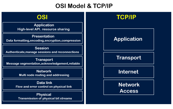
The diagram below illustrates a comparison between the OSI and TCP/IP models, showcasing the associated protocols.

Comparison of the OSI model and the TCP/IP model

The TCP/IP model closely resembles the OSI reference model in structure, although it condenses the seven layers of OSI into four layers:

  • The Application layer in the TCP/IP model aligns with the Session, Presentation, and Application Layers of the OSI model.
  • The Transport layer in the TCP/IP model corresponds to the Transport Layer in the OSI model.
  • The Network layer in the TCP/IP model aligns with the Network Layer in the OSI model.
  • The Host-to-Network layer in the TCP/IP model corresponds to the Physical and Data Link Layers of the OSI model.

Functions of the Layers of the TCP/IP Model

1. Host to Network Layer:

  • This layer operates as a fusion of protocols from the physical and data link layers, supporting all standard protocols within these layers.
  • It acts as the bridge between the higher-level protocols and the physical network, ensuring seamless communication by integrating the functionalities of both the physical and data link layers.

2. Network Layer:

  • Also known as the Internetwork Layer, it houses the Internetworking Protocol (IP) responsible for transmitting data from source to destination.
  • The Internetworking Protocol (IP) is a connectionless and unreliable protocol, offering a best-effort delivery service. There is no error checking in IP; instead, it relies on underlying layers for data transmission.
  • IP divides data into packets or datagrams of the same size. Each packet is independent, allowing it to be transported across different routes and potentially arriving out of order at the receiver.
  • Being connectionless, IP packets find the best possible path to reach the destination without a predefined setup between the sender and receiver.
  • Due to the lack of guarantees about data delivery, IP is considered an unreliable protocol. Packets may get dropped along various routes during transmission.
  • Despite its unreliability, IP is not weak or useless; it efficiently provides only the necessary functionality for transmitting data, ensuring maximum efficiency.
  • The Network layer is associated with four other protocols:
    1. ARP
    2. RARP
    3. ICMP
    4. IGMP
  • These protocols contribute to the overall functionality of the Network layer, addressing various aspects of data transmission and communication.

i. ARP – Address Resolution Protocol:

  • Utilized to determine the physical address of a device on a network when its logical address is already known.
  • The physical address, a 48-bit identifier imprinted on the NIC or LAN card, corresponds to the Internet Address, commonly known as the IP address, which uniquely and universally identifies the device.
  • In essence, ARP facilitates the translation between the logical and physical addresses, enabling seamless communication within the network.

iii. RARP – Reverse Address Resolution Protocol:

  • Employed by a device within a network to discover its Internet address when it possesses knowledge of its physical address.
  • In practical terms, RARP serves as a mechanism for a device to obtain its logical (Internet) address based on the known physical address. This is particularly useful in certain network configurations and scenarios.

iii. ICMP – Internet Control Message Protocol:

  • Functions as a signaling mechanism to notify the sender of issues with datagrams that arise during transit.
  • Primarily utilized by intermediate devices, such as gateways, when they encounter problems like a corrupt datagram.
  • In the event of an issue, ICMP enables the intermediate device to send a message back to the sender, providing crucial information about the encountered problem. This mechanism aids in efficient network troubleshooting and maintenance.

iv. IGMP – Internet Group Message Protocol:

  • Serves as a mechanism facilitating the transmission of the same message to a designated group of recipients.
  • In practical terms, IGMP is essential for enabling efficient communication within multicast groups on a network. It ensures that messages are delivered to the intended audience, optimizing network performance for group-based communications.

3. Transport Layer

Transport layer protocols are accountable for efficiently transmitting data between processes on one machine to their corresponding processes on another machine. Within the transport layer, three primary protocols play distinct roles:

  1. TCP
  2. UDP
  3. SCTP

I. TCP – Transmission Control Protocol

TCP, or Transmission Control Protocol, is a reliable and connection-oriented protocol. This means that a connection is first established between the sender and receiver before data transmission begins, ensuring a secure and ordered exchange.

TCP strategically organizes the data it receives from the upper layer into segments. Each segment is assigned a sequence number, a crucial element used at the receiving end for the accurate reordering of data. This sequencing mechanism enhances the reliability and integrity of data transmission, ensuring that information reaches its destination in the intended order.

II. UDP – User Datagram Protocol

UDP, or User Datagram Protocol, is a straightforward protocol designed for direct process-to-process transmission. It operates as an uncomplicated and connectionless protocol, particularly suitable for applications that do not necessitate flow control or error control.

Unlike TCP, UDP does not establish a connection before data transmission and does not offer the same level of reliability. Instead, it simply appends essential information such as port address, checksum, and length to the data received from the upper layer. This minimalist approach makes UDP a lightweight option for scenarios where simplicity and low overhead are priorities over guaranteed delivery and error correction.

III. SCTP – Stream Control Transmission Protocol

SCTP, or Stream Control Transmission Protocol, is a recently introduced addition to the transport layer of the TCP/IP protocol suite. This protocol stands out by combining the distinctive features of both TCP and UDP.

Primarily employed in applications such as voice over the Internet, SCTP boasts a considerably broader range of applications. Its versatility makes it well-suited for scenarios where a reliable and message-oriented approach is essential, offering advantages in both reliability and flexibility. The integration of features from TCP and UDP positions SCTP as an adaptable solution for diverse communication needs.

4. Application Layer

The Application Layer serves as a consolidation of the Session, Presentation, and Application Layers from the OSI model. It is responsible for defining high-level protocols essential for various applications, including File Transfer (FTP), Electronic Mail (SMTP), Virtual Terminal (TELNET), Domain Name Service (DNS), and more. This layer acts as the interface between software applications and the underlying network, ensuring seamless communication and interoperability across diverse services.

Addressing in TCP/IP

Addressing in TCP/IP refers to the process of assigning unique identifiers to devices within a network to facilitate communication.

The TCP/IP protocol suite involves 4 different types of addressing:

    1. Physical Address
    2. Logical Address
    3. Port Address
    4. Specific Address

1. Physical Address

  • The Physical Address, also known as the link address, is the most basic level of addressing.
  • It is localized to the network to which the device is connected and is unique within that specific network.
  • Found at the data link layer, the physical address is typically embedded in the frame for communication.
  • Often referred to as the MAC (Media Access Control) address, it consists of 6 bytes (48 bits) and is permanently imprinted on the Network Interface Card (NIC) of the device.
  • The size of the physical address may vary depending on the network type; for instance, Ethernet networks commonly use a 6-byte MAC address.

2. Logical Address

  • Logical Addresses are essential for universal communication, especially when data traverses different networks.
  • Unlike physical addresses, which are local to specific networks and may be duplicated across multiple networks, logical addresses ensure seamless source-to-destination data delivery in an internetwork environment.
  • Also known as an IP (Internet Protocol) Address, the Logical Address is employed at the network layer to universally identify devices like computers and routers.
  • IP addresses are globally unique, overcoming the limitations of local physical addresses. Currently, two versions of IP addresses are in use:
    • IPv4: A 32-bit address format.
    • IPv6: A 128-bit address format, designed to accommodate the growing number of connected devices on the Internet.

3. Port Address

  • While a logical address ensures data transmission from source to destination, both the source and destination devices often host multiple processes engaged in communication.
  • For instance, Users A & B may chat using Google Talk, while Users B & C exchange emails via Hotmail. Although the IP address facilitates data transmission from A to B, it doesn't specify the particular process on the destination device.
  • To address this, a Port Address comes into play, providing a means to identify the source and destination processes. This ensures that data is not only delivered to the correct device but also to the correct process on that device.
  • A Port Address serves as a name or label for a process and is a 16-bit identifier. For example, TELNET uses port address 23, and HTTP uses port address 80. Port addressing enhances the precision of data delivery in scenarios involving multiple processes on communicating devices.

4. Specific Address

  • Port addresses facilitate data transmission from process to process, but challenges may arise in cases where multiple instances of the same process exist.
  • For instance, consider Users A, B, and C chatting via Google Talk, each having two chat windows open. User A has two chat windows for B & C, and similarly, User B and User C have two chat windows each.
  • While a port address ensures data delivery to the correct process (Google Talk) on User B, there are now two available windows for User A & C on B where the data can be delivered.
  • To overcome this, specific addresses come into play. These user-friendly addresses help identify different instances of the same process. For example, multiple tabs or windows of a web browser operate under the same process (HTTP) but are identified using Uniform Resource Locators (URLs), serving as specific addresses to distinguish between various instances of the process.
Reading Material
Transmission Media and Network Devices Lesson 11 of 24
In Progress

Transmission Media

Transmission media, in simple terms, refer to the physical path that conveys information from a source to its destination. This medium can encompass free space, metallic cables, or fiber-optic cables, facilitating the transmission of data through electromagnetic signals.

Categories of Transmission Media:

In the realm of data communication, transmission media fall into two main categories:

  1. Guided Media
  2. Unguided Media

Transmission media can be broadly categorized into guided and unguided types. Guided media, exemplified by twisted-pair cables, coaxial cables, and fiber-optic cables, establish a defined path for data transmission. This type is suitable for point-to-point or multipoint communication, where considerations like the medium and cable length play a vital role.

Categories of Transmission Media

On the flip side, unguided media operate in free space, allowing data transmission without a specific physical pathway. In this mode, electromagnetic signals are employed for communication, with careful attention to managing potential noise interference.

1. Guided Media

Guided media establishes a physical connection, serving as a conduit between devices. When a signal travels through these media, it is directed and confined by the physical medium itself. Examples of guided media include twisted-pair and coaxial cables, utilizing metallic conductors to carry signals as electric currents. Optical fiber cables are also guided media, accepting and transporting signals in the form of light.

Twisted Pair Cable:

A twisted pair cable consists of two conductors, typically made of copper, each individually insulated and then wound together, as depicted in the figure below.

Twisted Pair Cable

One of these wires serves to transmit signals to the receiver, while the other functions solely as a ground reference. The receiver utilizes the difference between these two wires. However, when the sender transmits a signal on one wire, interference (noise) and crosstalk may impact both wires, introducing unwanted signals.

To mitigate the impact of undesirable signals, the wires are twisted. If the wires run parallel, the effects of noise or crosstalk aren't the same on both wires due to their different locations relative to the sources (e.g., one closer and the other farther). Twisting the pair helps maintain balance.

The data rate supported over a twisted pair is inversely proportional to the square of the line length. A maximum transmission distance of 1 km can be achieved for data rates up to 1 Mb/s. For analog voice signals, amplifiers are required approximately every 6 km, and for digital signals, repeaters are needed every 2 km.

Unshielded vs. Shielded Twisted-Pair Cable:

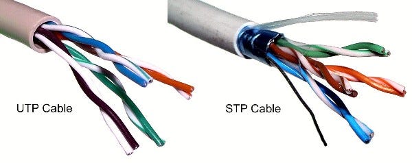
The prevalent type of twisted pair cable extensively used in communications is known as Unshielded Twisted Pair (UTP). Additionally, IBM has introduced Shielded Twisted Pair (STP) for specific applications. STP cable incorporates a metal shield or braided mesh covering that envelops each pair of insulated conductors. While the metal shielding enhances cable quality by preventing noise or crosstalk interference, it adds bulk and increases cost. The figure illustrates the distinction between UTP and STP.

Unshielded and Shielded Twisted-Pair cable

Categories of Unshielded Twisted Pair (UTP) Cable:

The Electronic Industries Association (EIA) has established standards categorizing Unshielded Twisted-Pair (UTP) cables into seven categories, each tailored for specific purposes.

  • CAT1: Primarily used for telephone wires, particularly by telecommunication companies offering ISDN and PSTN services.
  • CAT2: Employed mostly in token ring networks, supporting speeds up to 4 Mbps. While almost obsolete, it meets the requirements for the almost extinct 10 Mbps speed.
  • CAT3, CAT4, CAT5/5e, CAT6 & CAT7: Geared towards network wire specifications, capable of supporting computer network and telephone traffic. CAT5e, the most popular, replaced old coaxial cables due to the growing demand for faster and more reliable networks.
  • CAT3 and CAT4: Utilized in Token Ring networks, where CAT3 supports a maximum of 10 Mbps, while CAT4 extends the limit to 16 Mbps. Both categories have a maximum range of 100 meters.
  • CAT5e: Improved version of CAT5, featuring enhanced crosstalk specifications, supporting speeds of up to 1 Gbps. It is the widely used cabling specification globally.
  • CAT6: Initially designed to support gigabit Ethernet, it is similar to CAT5e but includes a physical separator between pairs to reduce electromagnetic interference. CAT6 can handle speeds of 1 Gbps for lengths up to 100 meters, and 10 Gbps for up to 55 meters.
  • CAT7: A newer specification designed for speeds of 10 Gbps at lengths up to 100 meters. It features four individually shielded pairs along with an additional cable shield to protect signals from crosstalk and electromagnetic interference.

Understanding Unshielded Twisted-Pair Connectors (RJ45):

The prevalent Unshielded Twisted-Pair (UTP) connector, widely known as RJ45, holds significance in networking and is an abbreviation for "registered jack." In an Ethernet cable, eight color-coded wires are intricately twisted into four pairs, each adhering to a common color theme. The RJ45 connector utilizes an 8P8C modular connector, denoting 8 Positions and 8 Contacts. This keyed connector ensures a single insertion orientation.

RJ 45 Connector


Characteristics of Twisted Pair Cable:

  • Requires amplifiers every 5-6 km for analog signals.
  • Demands repeaters every 2-3 km for digital signals.
  • Attenuation strongly depends on frequency.
  • Susceptible to interference and noise.

Applications:

  1. Used in telephone lines, providing voice and data channels.
  2. The local loop, linking subscribers to central telephone offices, commonly employs UTP cables.
  3. DSL lines also utilize UTP cables.
  4. UTP cables are prevalent in LANs such as 10Base-T and 100Base-T.

Advantages and Disadvantages

Advantages:

  • Inexpensive, widely available, and lightweight.
  • Flexible and easy to install.

Disadvantages:

  • Vulnerable to interference and noise.
  • Analog signals require repeaters every 5-6 km.
  • Digital signals necessitate repeaters every 2-3 km.
  • Relatively low bandwidth (3000Hz).

Coaxial Cable:

A coaxial cable, often referred to as "coax," consists of two conductors, allowing it to operate across a broader range of frequencies. It features a hollow outer cylindrical conductor that surrounds a single inner wire conductor. The inner conductor is held in place by regularly spaced insulating rings or a solid dielectric material. The outer conductor is protected with a shield or coat.

A single coaxial cable typically has a diameter ranging from 1 to 2.5 cm. Its design enables it to be used over longer distances and supports a larger number of channels on a common line compared to twisted pair cables. Coaxial cables find applications in both baseband and broadband communications.

In baseband Local Area Networks (LANs) , data rates fall within the range of 1 KHz to 20 MHz, covering distances up to 1 Km. For broadband applications, these cables offer data rates ranging from 300 to 400 MHz. The versatility of coaxial cables makes them suitable for various communication scenarios, ensuring reliable transmission over extended distances.

In this unit, our emphasis shifts to the exploration of specific guided media, including coaxial cable, twisted pair, and fiber optic cable. These media play essential roles in various communication scenarios.

Standards

Coaxial cables are categorized based on their Radio Government (RG) ratings. Each RG number signifies a specific set of physical characteristics, including the inner conductor's wire size, the thickness and type of the inner insulator, the shield's construction, and the size and type of the outer casing. Each cable, defined by an RG rating, is tailored for a specific purpose.

Category

Impedance

Use

RG-59

75Ω

Cable Television

RG-58

50Ω

Thin Ethernet

RG-11

50Ω

Thick Ethernet

Understanding Coaxial Cable Connectors:

For connecting coaxial cables to various devices, coaxial connectors play a crucial role. The widely utilized type of connector today is the Bayone-Neil-Concelman, abbreviated as the BNC connector. There are three key types of connectors:

1. BNC Connector:

  • Purpose: Links the cable's end to a device, like a TV set.

2. BNC T Connector:

  • Application: Employed in Ethernet networks to extend connections to computers or other devices.

3. BNC Terminator:

  • Function: Positioned at the cable's end to prevent signal reflection.

These connectors serve distinct purposes in establishing and optimizing connections in coaxial cable setups.

Coaxial Cable Connector

Applications

The coaxial cable serves as a versatile transmission medium employed in various applications, including:

  • Television distribution
  • Long-distance telephone transmission
  • Short-run computer system links
  • Local area networks

Coaxial cable was extensively used in analog telephone systems, capable of carrying 10,000 voice signals. In digital telephone systems, it conveyed digital data at speeds up to 600 Mbps. However, fiber optic cables have largely replaced coaxial cables in telephone systems today. Cable TV networks initially used coaxial cables extensively, but fiber-optic cables have progressively taken over, with coaxial cables remaining at network boundaries near customer premises. Digital TV commonly employs RG-59 coaxial cable.

Advantages & Disadvantages

Advantages:

  • Greater channel capacity than twisted pair.
  • Greater bandwidth compared to twisted pair.
  • Lower error rate (Approx. 10^-9 bps)

Disadvantages:

  • Installation can be challenging.
  • Higher installation costs.
  • Susceptible to noise interference.

Fiber Optic Cable:

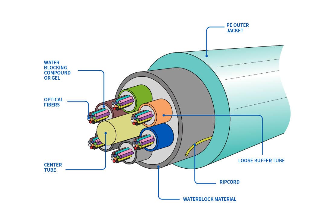
Instead of relying on electric signals, fiber optic cables utilize light to transmit data, functioning on the principle of total internal reflection. Composed of glass fibers finer than a human hair, these cables guide light beams across extensive distances. An optical fiber comprises a slender glass core enveloped by a cladding layer, with some fibers being made of plastic, which, though easier to install, has limited light transmission compared to glass.

Fiber optic Cable

Types of Fiber-Optic Cable Connectors:

  1. Subscriber Channel Connector: Primarily employed in cable TV, featuring a push/pull locking system.
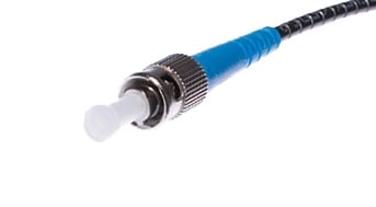
  2. Straight-Tip Connector: Connects cable to networking devices, employing a bayonet locking system, known for reliability.
  3. MT–RJ Connector: Comparable in size to RJ45, providing versatility in applications.
Fiber Optic cable connector


Applications:

  • Commonly used as backbone networks (e.g., SONET) due to cost-effective wide bandwidth.
  • Hybrid networks, combining optical fiber and coaxial cable, are often employed by some cable TV companies.
  • In LANs such as 100Base-FX network (Fast Ethernet) and 1000Base-X.

Advantages and Disadvantages

Advantages:

  • High bandwidth capacity (multiple gigabits per second).
  • Extended distances between devices (ranging from 2 to over 60 kilometers).
  • Immunity to electromagnetic interference.
  • Simultaneous transmission and reception of very high frequencies.
  • Less signal attenuation, lightweight, and enhanced tapping immunity.

Disadvantages:

  • Installation and maintenance can be challenging.
  • Unidirectional light propagation and associated costs.

Choosing Fiber-Optic Cable:

  • Opt for fiber-optic cable for high-speed, secure data transmission over long distances.
  • Avoid it if on a tight budget without the expertise for proper installation and device connection.

Characteristic

Twisted Pair Cable

Coaxial Cable

Optical Fiber

Signal Transmission Medium

Electrical form over metallic conducting wires   

Inner conductor of the cable

Optical form over a glass fiber

Noise Immunity

Low, leading to more distortion

Higher due to the presence of shielding conductor

Higher, unaffected by electrical noise

Effect of External Magnetic Field

Affected

Less affected                                   

Not affected                        

Short Circuit Possibility

Possible

Possible

Not Possible

Cost

Cheapest

Moderately expensive

Expensive

Data Rate Support

Low

Moderately High

Very High

Bandwidth

Low

Moderately High

Very High

Installation

Easy

Fairly easy

Difficult

This table provides a comparison between Twisted Pair Cable, Coaxial Cable, and Optical Fiber based on various characteristics, including signal transmission, noise immunity, susceptibility to external factors, short circuit possibility, cost, data rate support, bandwidth, and ease of installation.

2. Unguided (Wireless) Medium:

Unguided media, commonly known as wireless communication, enables data transmission without relying on a physical conductor. Wireless electromagnetic signals serve as the means for sending data.

Types of Wave Propagation:

Before delving into wireless transmission media types, it's crucial to understand how wireless signals travel. These signals can propagate through three distinct methods:

i. Ground-wave Propagation:

  • Follows the contour of the earth.
  • Propagates considerable distances.
  • Frequencies up to 2 MHz.
  • Example: AM radio.
Ground-wave propagation


ii. Sky-wave Propagation:

  • The signal is reflected from the ionized layer of the atmosphere back down to Earth.
  • Can travel multiple hops between the ionosphere and the earth's surface.
  • Reflection effect caused by refraction.
  • Examples: Amateur radio, CB radio.
Sky-wave propagation


iii. Line-of-sight Propagation:

Transmitting and receiving antennas must be within the line of sight.
  1. Satellite communication – signal above 30 MHz not reflected by the ionosphere.
  2. Ground communication – antennas within effective line of sight due to refraction.
Line-of-sight propagation


Types of Unguided (Wireless) Medium:

There are three main types of unguided media:

Categories of the wireless medium


1. Radio Waves:

  • Frequency range: 3 KHz to 1 GHz.
  • Omni-directional propagation.
  • Suitable for long-distance broadcasting.
  • Can penetrate walls at low and medium frequencies.

2. Microwaves:

  • Frequency range: 1 to 300 GHz.
  • Unidirectional propagation.
  • Requires alignment of transmitting and receiving antennas.
  • Line-of-sight propagation; is effective for focused communication.

3. Infrared:

  • Frequency range: 300 GHz to 400 GHz.
  • Used for short-range communication.
  • High-frequency signals that cannot penetrate walls.
  • Prevents interference between different systems.
  • Ideal for transmitting digital data at high speeds.

Choice of Transmission Media:

The selection of a transmission medium is critical, impacting network cost, operating speed, and error rates. A transmission medium should be durable, reliable, cost-effective, immune to noise, and easy to install, maintain, and reconfigure.

Comparison between Guided and Unguided Media

Guided media and unguided media differ from each other in the following ways.

GuidedMedia

Unguided Media

The signal energy is contained and guided within a solid medium

The signal energy propagates in the form of unguided electromagnetic waves.

Examples of wired media are twisted-pair wires, coaxial cables, and optical fiber cables.

Microwaves, radio waves, and infrared lights are examples of wireless media.

Used for point-to-point communication

Used for radio broadcasting in all directions

Wired media leads to discrete network topology

Wireless media leads to a continuous network topology

Additional transmission capacity can be procured by adding more wire

It is not possible to procure additional capacity.

Installation is costly and time-consuming

Installation needs less time and money

Attenuation depends exponentially on the distance.

Attenuation is proportional to the square of the distance.

Reading Material
Transmission Media and Network Devices Lesson 12 of 24
In Progress

Network Devices Overview

Local Area Networks are interconnected through various network devices operating at different Internet model layers. These devices can be categorized into five groups based on the layer in which they function:

  • Devices below the Physical Layer: Examples include Passive Hubs.
  • Devices at the Physical Layer: Examples include Repeaters or Active Hubs.
  • Devices at the Physical and Data Link Layers: Examples include Bridges or two-layer switches.
  • Devices at the Physical, Data Link, and Network Layers: Examples include Routers or three-layer switches.
  • Devices Operating at All Five Layers: Examples include Gateways, often functioning as routers.

In this section, we will explore network devices operating across various layers:

Hub

Hubs are vital in LAN connectivity, serving as central connection points. They operate by receiving signals from individual computers and broadcasting these signals to all other stations within the hub.

Hub

Key Features:

  • Hubs typically feature 4 to 24 RJ-45 ports for twisted-pair cabling.
  • They include one or more uplink ports for connecting to other hubs.
  • Indicator lights display port link status, collisions, and other essential information.

Types of Hubs:

1. Passive Hubs:

  • Act as connectors, linking wires from different branches.
  • In a star-topology Ethernet LAN, a passive hub serves as the collision point.
  • Positioned below the physical layer in the Internet model.

2. Active Hubs:

  • Amplify signals before transmitting to other computers.
  • Function as Multiport Repeaters operating in the physical layer.
  • Ideal for establishing connections in a physical star topology.

Switch

A switch serves as a critical network device responsible for determining the path or circuit through which a signal travels from its source to the destination. It plays a pivotal role in directing data to the appropriate adjacent network point.

CISCO Switch

Switch Types:

1. Two-Layer Switch:

  • Operates at the physical and data link layers.
  • Functions as a bridge, connecting multiple LANs for enhanced performance.

2. Three-Layer Switch:

  • Functions at the network layer, akin to a router.
  • Routes packets based on logical addresses, facilitating efficient data transmission.

Switch Utilization:

  • In smaller networks, switches may be optional.
  • However, in expansive networks like the internet, where multiple routes are possible for transmitting a message, switches become essential.
  • The primary purpose of a switch is to intelligently select the optimal path, effectively managing bandwidth in large-scale networks.

Router

A router serves as a sophisticated three-layer device, guiding packets based on their logical addresses. Typically linking Local Area Networks (LANs) and Wide Area Networks (WANs) on the internet, routers utilize dynamic routing tables to make informed decisions about the most efficient route.

Cisco Router


Key Router Components:

  • Routing Tables: These tables dynamically update through routing protocols, guiding the router in route decisions.
  • Hardware: Physical interfaces connecting to various networks on the internet.
  • Software: Comprising the operating system and routing protocols, essential for router functionality.
Working on Router, switch, Modem

Router Functions:

  • Path Determination: Routers excel in determining the optimal path for a particular transmission among available options.
  • Logical and Physical Addressing: Utilizing logical and physical addressing, routers connect separate networks.
  • Logical Network Segmentation: Organizing the extensive network into logical sub-networks allows for efficient data exchange.
  • Packet Grouping: Data is organized into packets, each carrying both a physical device address and a logical network address.
  • Store-and-Forward Technique: Routers temporarily store and then forward messages, implementing a store-and-forward technique to enhance transmission efficiency.

Repeater

Repeaters, functioning solely in the Physical Layer, play a critical role in preserving signal integrity within a network. As signals traverse a network, they encounter a limit to their travel distance before succumbing to attenuation and corruption. A repeater steps in just before this weakening point, receiving the signal, regenerating its original bit pattern, and sending forth a refreshed signal.

Matrox Veos Repeater

 Repeaters offer a strategic solution for expanding the physical reach of a network. By segmenting the cable into manageable sections, repeaters overcome cable length limitations. Installed between these segments, they operate as two-port nodes, receiving frames from one port, regenerating them, and forwarding them to the other port.

Repeater vs. Amplifier:

While an amplifier indiscriminately boosts all signals, including noise, a repeater distinguishes itself by not amplifying but regenerating the signal. It meticulously recreates a bit-for-bit copy of the original signal at its original strength. This selective regeneration ensures that the signal maintains its precision despite encountering some noise along the way.

The functionality of a Repeater:

The primary function of a repeater is to regenerate the original signal by creating an exact copy, bit for bit, at the original strength. Its crucial role lies in intercepting the signal before it degrades to a point where noise interferes with the meaning of its bits. Placing a repeater strategically on the network ensures it captures the signal before any degradation, allowing it to read the signal with enough precision to faithfully replicate the intended voltages. This precision is vital, as even slight alterations in bit voltage can impact the signal's accuracy without entirely compromising its identity.

Bridges

Bridges operate in both the physical and data link layers. In the physical layer, they regenerate signals, and in the data link layer, they examine MAC addresses (physical addresses) of the source and destination in frames. MAC stands for Media Access Control.

Bridges

Unlike repeaters, bridges have filtering capabilities. They maintain a table mapping addresses to ports, allowing them to determine whether a frame should be forwarded or dropped based on its destination address. If forwarding is required, the bridge specifies the port for the transmission.


Gateway

A gateway is a versatile computer that operates across all five layers of the Internet or all seven layers of the OSI model. It manages messages, addresses, and protocol conversions necessary for delivering messages between networks. Essentially, a gateway interprets application messages and can serve as a connecting device between networks using different models.

Gateway

Commonly, gateways connect a LAN and a Mainframe computer by adjusting protocols and transmitting packets between two distinct networks. For instance, a gateway can link a network following the OSI model with another using the Internet model. When a frame arrives from the first network, the gateway moves it up to the OSI application layer, extracting the message.

Gateways offer maximum flexibility in internetworking communications, allowing connections between networks with different models. However, this flexibility comes at the expense of a higher price, a more complex design, and increased demands for implementation, maintenance, and operation. Gateways also provide security features and can filter out unwanted application-layer messages.

In comparison to other network devices, gateways are slower than routers, and routers are slower than bridges unless the processing capability is proportionately increased.

Reading Material
Data Link Layer Protocols Lesson 13 of 24
In Progress

Introduction

As previously mentioned in the context of network models, the Physical Layer is chiefly tasked with physically transmitting " bits " over a communication medium. Positioned between the Network Layer and the Physical Layer, the Data Link Layer takes on the responsibility of guaranteeing the delivery of data, presented as " packets " from the Network Layer to the correct device on the network. This process adheres to the transmission standards set by the Physical Layer.

In this section, we will delve into the functions of the Data Link Layer and explore its associated protocols.

Reading Material
Data Link Layer Protocols Lesson 14 of 24
In Progress

Data Link Layer Protocols

To ensure accurate data delivery, the Data Link Layer provides the following services:

1. Identification of Physical Addresses:

  • Identifying the physical addresses of both sending and receiving devices is a crucial service provided by the Data Link Layer.

2. Formatting Packets into Frames:

  • The Data Link Layer formats Network Layer " packets " into frames, attaching physical addresses for proper transmission.

3. Sequencing and Re-sequencing:

  • Frames transmitted out of sequence are managed through sequencing and re-sequencing mechanisms, enhancing data integrity.

4. Error Detection and Media Access Control:

  • The Data Link Layer performs error detection and controls media access, ensuring reliable communication.

Data Link Sublayers

The IEEE has categorized the Data Link Layer into two sub-layers:

i. Logical Link Control (LLC) Sub-layer (802.2):

  • Manages communications over a single network link, supporting both connection-oriented and connectionless services.
  • Incorporates flow control using ready/not ready codes and sequence control for transmitted frames.
  • Enables independent functioning from underlying technologies, providing versatility to network layer protocols.

ii. Media Access Control (MAC) Sublayer (802.3 & 802.5):

  • Maintains unique physical device addresses, known as MAC Addresses, facilitating targeted message transmission.
  • MAC addresses are burned into the Network Interface Card (NIC) during manufacturing.
  • Handles media access technologies, ensuring efficient and organized network communication.
Data Link Sublayers
Reading Material
Data Link Layer Protocols Lesson 15 of 24
In Progress

Common Data Link Layer Protocols

1. Ethernet and Token Ring:

  • Ethernet and Token Ring stand out as widely used LAN Layer 2 Protocols, defined by IEEE specifications 802.3 and 802.5, respectively.

2. Media Access Control (MAC) Protocols:

  • IEEE 802.3 and 802.5 standards, defining station access to the media, are categorized as Media Access Control (MAC) protocols. These protocols are integrated into the MAC sublayer of the Data Link Layer.
  • Both Ethernet and Token Ring protocols incorporate another specification in the Data Link Layer known as Logical Link Control (LLC) 802.2.

3. Logic Link Control (LLC) 802.2:

  • IEEE 802.2 is specifically crafted to provide common functions shared by both Ethernet and Token Ring protocols.
  • While 802.3 and 802.5 focus on Data Link functions related to either Ethernet or Token Ring topologies, 802.2 serves as a unifying element designed to harmonize functionalities for both.
Common Data Link Layer Protocols

Ethernet (IEEE 802.3)

Ethernet, developed by Xerox in 1970, was initially implemented through thicknet cable, operating at 10 Mbps. It has become one of the most widely used LAN protocols. The original version of Ethernet, designed for over 100 computers on a 1 km cable, has evolved into a standard that encompasses three principal categories.

Ethernet / IEEE 802.3 Specifications:

  • Ethernet/IEEE 802.3 operates at 10 Mbps on coaxial and twisted-pair cables. The IEEE 802.3 specification allows for a 100 Mbps transfer as well.

Types of Ethernet:

Ethernet, a network standard for data communication, utilizes twisted pair or coaxial cables, connecting computers to the Internet or a network. It is classified into two types based on speed:

  1. Fast Ethernet: Designed to compete with protocols like FDDI, it operates at 100 Mbps over twisted pair cables.
  2. Gigabit Ethernet: Operates at 1000 Mbps (1 Gbps) over fiber and twisted-pair cables, designed to connect two or more stations.

Ethernet Properties:

  • Uses 10Mbps/100Mbps broadcast bus technology.
  • The transceiver passes all packets from the bus to the host adapter.
  • The host adapter chooses some packets and filters others.
  • Best-effort delivery, where the hardware provides no information to the sender about whether the packet was delivered.
  • If the destination machine is powered down, packets will be lost.
  • TCP/IP protocols accommodate best-effort delivery.

Fast Ethernet Goals:

  • Upgrade the data rate to 100 Mbps.
  • Maintain compatibility with Standard Ethernet.
  • Retain the same 48-bit address, frame format, minimum, and maximum frame length.

Gigabit Ethernet:

  • Designed for connecting two or more stations, supporting point-to-point connections.
  • Operates at 1000 Mbps (1 Gbps) over fiber and twisted-pair cables.

Broadcasting:

  • Ethernet operates in a broadcast-based environment, where all stations see all frames on the network. After any transmission, each station must examine every frame to determine its intended recipient. Frames identified for a specific station are then passed to a higher-layer protocol.
Reading Material
Data Link Layer Protocols Lesson 16 of 24
In Progress

Token Ring/IEEE 802.5

Where Did Token Ring Come From?

Token Ring, developed in the 1970s by IBM, was later standardized by IEEE as IEEE 802.5. Initially, it was the most prevalent network implementation, and while it is currently surpassed by Ethernet in usage, IBM continues to employ Token Ring in its network design.

Token Passing Mechanism:

  • Token passing in Token Ring entails circulating a token or a small frame throughout the network.
  • The device in possession of the token holds the "right-of-way" to transmit information around the ring.

Token Ring and Ethernet represent two distinct approaches to networking. While Ethernet utilizes a bus or star topology with a contention-based access mechanism, Token Ring employs a ring topology with a token-passing access mechanism. In a Token Ring network, devices are organized in a physical ring or star-wired ring, and the token circulates in a predictable order. This ensures orderly access to the network, preventing collisions and optimizing data transmission.

Despite its historical significance and once being a dominant technology, the Token Ring has gradually declined in popularity due to the widespread adoption of Ethernet. However, it still finds niche applications, especially in legacy systems where Token Ring infrastructure remains in use.

Reading Material
Data Link Layer Protocols Lesson 17 of 24
In Progress

Medium Access Control

In systems where multiple users share a common channel, leading to potential conflicts, these scenarios are termed contention or collision. The time during which conflicts may occur is referred to as the contention period. The MAC sub-layer of the Data Link Layer is responsible for collision resolution. Contention arises when there are instances when it is not suitable to send data across the media.

Multiple Access Protocols:

Multiple Access Protocols can be categorized into three groups:

Taxonomy of Multiple Access Protocols


1. Random Access:

  • In random access or contention methods, no station holds superiority over another, and none is assigned control over another. Each station allows or does not allow another station to send without any inherent hierarchy.

2. Controlled Access:

  • In controlled access, stations consult with one another to determine which station has the right to send. A station cannot transmit unless it has been authorized by other stations, introducing a controlled hierarchy.

3. Channelization:

  • Channelization is a multiple-access method in which the available bandwidth of a link is shared in time, frequency, or through code among different stations. This method helps allocate specific segments of the channel to individual stations, reducing the likelihood of collisions.

Understanding these multiple access protocols is crucial for optimizing network efficiency. Random access is often employed in scenarios where fairness is prioritized, while controlled access provides a more structured and controlled approach. Channelization, on the other hand, allocates dedicated portions of the channel to different stations, minimizing conflicts and enhancing overall network performance.

Random Access Protocols

Aloha Protocols

The Aloha protocol originated from a project at the University of Hawaii, aiming to facilitate data transmission among computers on different Hawaiian Islands through radio transmissions. Communication primarily occurred between remote stations and a central site known as Menehune, or vice versa. All messages sent to Menehune utilized the same frequency. Upon receiving an intact message, Menehune broadcasted an acknowledgment (ACK) on a distinct outgoing frequency, which was also used for messages from the central site to remote computers. All stations monitored this second frequency for incoming messages.

Pure Aloha

Pure Aloha, a fully decentralized and unspotted protocol, operates as a random access protocol with a straightforward implementation. Its guiding principle is simplicity: "When you want to talk, just talk!" Nodes desiring transmission send packets on their broadcast channel without regard for other ongoing transmissions. However, a significant drawback is the lack of knowledge about successful reception. To address this, Pure Aloha incorporates a mechanism where, after transmitting, a node expects an acknowledgment within a finite time. If none is received, the data is retransmitted. While effective in small networks with low loads, this approach falters in larger, high-load networks, prompting the development of Slotted Aloha.

Pure Aloha

Slotted Aloha

Similar to Pure Aloha but with a different approach to transmissions, Slotted Aloha introduces a delay before sending. It divides the timeline into equal slots, allowing transmissions only at slot boundaries. Assumptions include fixed frame sizes, time divided into slots of size L/R seconds, nodes initiating transmissions only at slot beginnings, and synchronized nodes aware of slot start times. Collisions, detected by all nodes before a slot ends, are reduced significantly.

This synchronization minimizes collisions among nodes attempting to transmit simultaneously, leading to improved performance compared to Pure Aloha.

Carrier Sense Multiple Access (CSMA)

Carrier Sense Multiple Access (CSMA) operates on the principle of "sense before transmit" or "listen before talk." It aims to reduce, though not eliminate, the possibility of collisions during data transmission. The persistence of collision risk arises from propagation delay, as it takes a short amount of time for the first bit of a transmitted frame to reach all stations.

In CSMA, at time 't,' station B senses the medium and perceives it as idle because, at that moment, the first bits from station B have not yet reached station C. However, station C, unaware of B's transmission, also sends a frame. The collision of these two signals destroys both frames.

CSMA encompasses two distinct protocols: CSMA/CD (Carrier Sense Multiple Access with Collision Detection) and CSMA/CA (Carrier Sense Multiple Access with Collision Avoidance). These protocols offer different approaches to managing collisions and enhancing the efficiency of data transmission in network communication.

Carrier Sense Multiple Access Collision Detection (CSMA/ CD):

In CSMA/CD, a Local Area Network (LAN) is structured as a shared medium, requiring each device to wait for an appropriate time before transmitting data. Stations following this protocol in CSMA/CD agree upon terms and collision detection measures to ensure effective transmission. The protocol strategically determines which station will transmit at a given time, preventing data corruption on its way to the destination.

Algorithm:

In a CSMA/CD environment, any station in the network can transmit when the network is quiet.

1. Listen Before Transmit:

  • Before sending data, stations actively listen for ongoing traffic on the network.

2. Transmit if Idle:

  • If no other frame is present on the Ethernet, the station proceeds to send its data.

3. Wait in Case of Traffic:

  • If another frame is detected on the Ethernet network, the station patiently waits until it senses no traffic before initiating data transmission.

4. Collision Handling:

  • If two or more stations attempt to transmit simultaneously (collision), they stop, wait for a random amount of time, and reevaluate the network before retransmitting. Back-off algorithms determine the retransmission order for stations involved in the collision, assigning random order numbers to ensure fairness and efficient retransmission.

Carrier Sense Multiple Access with Collision Avoidance (CSMA/CA):

CSMA/CD faces limitations in certain wireless scenarios, particularly in "hidden node" problems. Imagine three nodes—A, B, and C—communicating wirelessly. B can communicate with both A and C, but A and C are beyond each other's range. If A and C attempt simultaneous communication with B, there's a risk of interference, and neither A nor C can detect it. To address this, CSMA/CA, a refined version suitable for wireless applications, was developed.

Algorithm:

1. Channel Status Check: When a frame is ready, the transmitting station checks if the channel is idle or busy.

2. Wait for Idle Channel: If the channel is busy, the station waits until it becomes idle.

3. Inter-frame Gap and Transmission: Once the channel is idle, the station waits for an Inter-frame Gap (IFG) time and then sends the frame.

4. Set Timer: After sending the frame, the station sets a timer.

5. Wait for Acknowledgement: The station waits for an acknowledgment from the receiver. If acknowledgment is received before the timer expires, the transmission is marked as successful.

6. Back-off and Retry: If no acknowledgment is received, the station waits for a back-off period and restarts the algorithm, aiming to improve the chances of successful transmission. This back-off mechanism helps avoid collisions and ensures efficient wireless communication.

Token Ring Method

In the Token Ring method, a distinctive approach is employed. A free token circulates within a ring when no device has data to send. When a device intends to transmit, it claims the free token by modifying bits in the 802.5 header to indicate token occupancy. Subsequently, the data is inserted into the ring following the token ring header.

Algorithm:

The fundamental steps for utilizing Token Ring when there's data to be sent are outlined below:

1. Listen for the Passing Token: Devices actively listen for the circulating token within the ring.

2. Token Availability Check: If the token is currently in use, the device waits for the next passing token.

3. Token Claim and Data Transmission: When the token is free, the device marks it as busy, appends the data, and transmits the data onto the ring.

4. Token Return and Data Removal: After completing a full revolution around the ring, the sender removes the data when the header with the busy token returns to the sender of that frame.

5. Free Token Transmission: The device, having sent its data, transmits a free token to enable another station to send a frame. This process ensures an orderly and efficient circulation of the token for data transmission within the Token Ring network.

Controlled Access Protocols

In controlled access protocols, stations collaborate to determine which station has the authorization to send data. The station seeking to transmit must receive approval from other stations. Three controlled-access methods are discussed:

Reservation

In the reservation method, a station must reserve before transmitting data. Time is divided into intervals, with a reservation frame preceding data frames in each interval. Each station has a dedicated mini slot in the reservation frame, making a reservation when needing to send a data frame. This method ensures orderly data transmission without collisions.


Polling

Polling is employed in topologies with a primary station and secondary stations. All data exchanges go through the primary device, which controls the link. The primary device determines which device can use the channel at a given time, preventing collisions using poll and select functions. However, a drawback is that if the primary station fails, the system becomes non-functional.

Select and Poll

Select

The select function is used by the primary device when it has data to send. The primary alerts the secondary devices to an upcoming transmission, transmitting a select (SEL) frame. This ensures that the secondary is prepared to receive the data.

Select

Poll

The poll function is used by the primary device to solicit transmissions from secondary devices. It asks each device if it has anything to send, and upon receiving a positive response, the primary reads the data and acknowledges its receipt.

Poll


Token Passing

In token passing, stations are organized in a logical ring, with each station having a predecessor and a successor. The right to access the channel is represented by a circulating token. The station holding the token has the authority to send data. When a station has data to send, it waits for the token from its predecessor, sends the data, and then passes the token to the next logical station. Token management is crucial to limit time, ensure token integrity, assign priorities, and facilitate the release of the token from low-priority to high-priority stations.

Channelization

Channelization, also known as channel partitioning, is a multiple-access method that involves sharing the available bandwidth of a communication link among different stations. This sharing can occur in three key dimensions: time, frequency, or through code. The purpose of channelization is to efficiently allocate resources and facilitate communication among multiple stations. In this section, we discuss three channelization protocols: FDMA, TDMA, and CDMA.

FDMA - Frequency Division Multiple Access

In Frequency Division Multiple Access (FDMA), the available bandwidth is partitioned into distinct frequency bands. Each station is assigned a dedicated frequency band for transmitting its data. This allocation remains constant, ensuring that each station has exclusive access to its designated frequency band throughout the communication.


Implementation:

1. Allocation and Band Pass Filters:

  • Each station is assigned a specific frequency band.
  • Stations employ bandpass filters to confine transmitter frequencies within their allocated bands.
  • Guard bands separate the allocated frequency bands to prevent interference between stations.

2. Channel Separation:

  • Allocated frequency bands are separated by guard bands, minimizing the risk of interference.
  • The visual representation in the figure illustrates the concept of FDMA, emphasizing the assigned frequency bands for different stations.

Key Characteristics:

  • Continuous Band Usage:
  • FDMA designates a fixed frequency band for the entire communication duration.
  • Well-suited for streaming data, allowing a continuous flow without the need for packetization.

Comparison with FDM:

  • Although FDMA and Frequency Division Multiplexing (FDM) seem conceptually similar, distinctions exist.
  • In FDM, low-pass channels are combined, modulated, and create a band-pass signal with shifted bandwidth.
  • FDMA operates at the data-link layer, where each station independently instructs its physical layer to generate a band-pass signal for the allocated frequency band. No physical multiplexer is involved at the physical layer, and signals are automatically band-pass filtered and mixed when transmitted to the common channel.

FDMA's distinct allocation strategy and continuous band usage make it a suitable choice for various communication systems, including cellular telephone networks, as explored further in another chapter.

TDMA - Time Division Multiple Access

In Time Division Multiple Access (TDMA) , stations collaborate to share the channel's bandwidth in sequential time slots. Each station is assigned a dedicated time slot, allowing exclusive transmission during that period. The core concept of TDMA is illustrated in the figure below.

The primary challenge in TDMA is achieving synchronization among stations. Each station must know the start and location of its designated time slot. Propagation delays, particularly in expansive network setups, pose difficulties in achieving precise synchronization. To address this, guard times, and synchronization bits (often referred to as preamble bits) are inserted, facilitating alignment and coordination.

It's crucial to highlight the distinction between TDMA and Time-Division Multiplexing (TDM). TDM operates at the physical layer, combining data from slower channels and transmitting them using a faster channel, employing a physical multiplexer for interleaving. In contrast, TDMA is a data-link layer access method. Each station instructs its physical layer to utilize the allocated time slot, eliminating the need for a physical multiplexer at the physical layer.

CDMA - Code Division Multiple Access  

Code Division Multiple Access (CDMA) originated decades ago and has become feasible with recent advancements in electronic technology. CDMA stands apart from FDMA and TDMA as it utilizes a unique approach where a single channel encompasses the entire bandwidth of the link, enabling all stations to transmit simultaneously without time-sharing.

To understand CDMA, consider the analogy of communication with different codes. Imagine a large room with diverse conversations happening simultaneously. Two people can converse privately in English, while another pair communicates in Chinese, and so forth. Despite the multiple conversations in the common space, each pair uses a distinct code or language, allowing for simultaneous and independent communication.

In CDMA, each station employs a unique code to differentiate its transmission from others, effectively utilizing the shared channel. This distinctive coding scheme contributes to CDMA's ability to support simultaneous transmissions without the need for time-sharing, making it a robust and efficient multiple-access method.

Reading Material
Data Link Layer Services Lesson 18 of 24
In Progress

Physical Addressing

When devices communicate on a network, they employ two distinct addressing concepts:

  • Physical Address: Also known as the MAC address, the physical address pinpoints the precise physical location of a computer device. It serves as a unique identifier for a given device on the network, facilitating its distinctive recognition.
  • Logical Address: Represented by the IP address, the logical address plays a vital role in identifying the network connection through which a device is linked to the network. Unlike the physical address, which focuses on the device itself, the logical address emphasizes the network connection used by the device.

Throughout this unit, we will explore the intricacies of the physical address within the network context.

Physical Address/The MAC Address

In computer networks, each device, such as a computer or printer, possesses a distinct and necessary identification number, akin to a Social Security Number for individuals in the US. This identifier, often known as the Physical or Hardware Address, is referred to as the MAC address. It is embedded in the Network Identification Card (NIC) during manufacturing and remains unique to that specific device.

Network Identification Card (NIC)

The MAC address, functioning as the physical hardware identifier, is crucial for the Data Link Layer to ensure accurate data delivery to the intended device. This address is assigned to every physical network connection on a device, resulting in one MAC address for a computer with a single interface and multiple MAC addresses for a router with several physical connections.

Distinguishing it from an IP address, a logical network address, and a MAC address is a fixed 48-bit identifier represented by 12 hexadecimal digits. The first 6 digits constitute the Organizational Unique Identifier (OUI), identifying the manufacturer, while the subsequent 6 digits typically represent a vendor-assigned serial number.

Importantly, a MAC address is unalterable and is permanently programmed into the device's hardware, residing in ROM (Read-Only Memory) during initialization and transferred to RAM (Random Access Memory) thereafter. Unlike an IP address, the MAC address does not affect routing messages between machines.

Reading Material
Data Link Layer Services Lesson 19 of 24
In Progress

Error Detection

Error detection is the straightforward process of determining whether any bit errors occurred while transmitting a frame. In most data links, a Frame Check Sequence or cyclic redundancy check field is included in the data link trailer to facilitate this. The field holds a value calculated and transmitted by the sender, and the goal is for this value to align with the calculation performed by the receiver.

It's crucial to note that error detection does not inherently involve error recovery. Many data links, such as Ethernet and token ring, do not offer error recovery. Nevertheless, within the 802.2 standard, an option known as LLC2 does provide error recovery capabilities.

Reading Material
Data Link Layer Services Lesson 20 of 24
In Progress

Identifying Encapsulated Data

In the last segment of a data link, the focus is on determining the nature of the data enclosed within the frame's data field. Upon receiving the data, the PC directs it to the relevant software based on the content within the data field. For instance, if the data originates from a Novell server, the PC transfers the data to the NetWare client code. Similarly, if the data is potentially from a Sun FTP server, the PC delegates the data to the TCP/IP code.
Reading Material
Data Link Layer Services Lesson 21 of 24
In Progress

Framing

Primarily, the initial function offered by the data-link layer is framing. At every node, the data-link layer is responsible for packaging the datagram (a packet received from the network layer) into a frame before transmitting it to the subsequent node. Conversely, when receiving a frame on the logical channel, the node must extract or de-capsulate the datagram from the frame. While we've illustrated only a header for a frame here, it's worth noting that frames may, in later chapters, incorporate both a header and a trailer. Various data-link layers exhibit distinct formats for framing, and at the data-link layer level, a packet is commonly referred to as a frame.
Reading Material
Data Link Layer Services Lesson 22 of 24
In Progress

Flow Control

In scenarios involving a producer and a consumer, the concept of flow control becomes crucial. When the producer generates items at a pace surpassing the consumption rate, item accumulation becomes inevitable. In the context of data transmission, the sending data-link layer, situated at one end of a link, acts as a producer of frames, while the receiving data-link layer at the opposite end functions as the consumer.

If the production rate of frames exceeds the consumption rate, frames at the receiving end must be buffered until they can be consumed or processed. However, maintaining an unlimited buffer size on the receiving side is impractical. Two options arise in this situation. The first option is to permit the receiving data-link layer to discard frames if its buffer reaches full capacity. The second option involves the receiving data-link layer sending feedback to the sending data-link layer, requesting it to either stop or slow down the frame transmission.

Various data-link-layer protocols employ diverse strategies for implementing flow control. It's worth noting that flow control also extends to the transport layer, where its significance is heightened.

Reading Material
Data Link Layer Services Lesson 23 of 24
In Progress

Error Control

In the data-link layer, a frame undergoes a process at the sending node, where it is converted into bits, transformed into electromagnetic signals, and transmitted through the transmission media. At the receiving node, electromagnetic signals are received, translated into bits, and assembled to reconstruct the original frame. However, due to the susceptibility of electromagnetic signals to errors, the received frame may contain errors.

The first step in managing errors is detection. Once an error is detected, the next step involves deciding whether to correct it at the receiving node or to discard the frame and initiate a retransmission from the sending node. It's crucial to acknowledge that error detection and correction are challenges encountered at every layer, whether it's node-to-node or host-to-host communication.

Reading Material
Data Link Layer Services Lesson 24 of 24
In Progress

Congestion Control

While a link may experience congestion due to an abundance of frames, leading to potential frame loss, it's notable that many data-link-layer protocols do not directly employ congestion control mechanisms to address this issue. Some wide-area networks may incorporate congestion control, but, as a general rule, congestion control is typically regarded as a concern more fitting for the network layer or the transport layer. This is primarily due to its end-to-end nature, where the overall network or transport layer is better positioned to manage and mitigate congestion-related challenges.
Introduction Quiz

Introduction to Data Communication Quiz

3 questions • Test your knowledge

Question 1
What is the key difference between data and information?
Question 2
In simplex data transmission mode, how does communication flow?
Question 3
Which of the following are the five fundamental components of any data communication system?
Networking Essential Quiz

Networking Essentials & Topologies Quiz

2 questions • Test your knowledge

Question 1
In a Star network topology, what happens if the central hub or switch fails?
Question 2
Which type of computer network is typically confined to a single room, building, or small campus?
Network Reference Models: OSI & TCP/IP Quiz

Network Reference Models (OSI & TCP/IP) Quiz

3 questions • Test your knowledge

Question 1
How many layers are defined in the standard ISO/OSI Reference Model?
Question 2
At which layer of the OSI model do IP addressing and packet routing decisions take place?
Question 3
What is the primary difference between TCP and UDP at the Transport Layer?
Transmission Media and Network Devices Quiz

Transmission Media & Network Devices Quiz

2 questions • Test your knowledge

Question 1
Which transmission medium uses light pulses to transmit data at very high speeds over long distances without electromagnetic interference?
Question 2
At which layer of the OSI model does a standard network switch operate by inspecting MAC addresses?
Data Link Layer Protocols Quiz

Data Link Layer Protocols Quiz

2 questions • Test your knowledge

Question 1
What is the primary function of the Media Access Control (MAC) sublayer in Ethernet networks?
Question 2
How many bits long is a standard Ethernet Physical (MAC) Address?
Data Link Layer Services Quiz

Data Link Layer Services Quiz

2 questions • Test your knowledge

Question 1
What is Framing in the context of Data Link Layer services?
Question 2
Which error detection mechanism appends a calculated polynomial checksum to each transmitted frame to verify data integrity?